
Titanic Tours – The Bridge
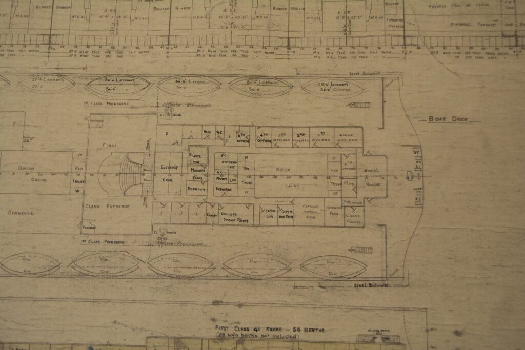
Titanic Tours – The Bridge A Titanic Connections Feature by Nicholas Dewitt The General Arrangement (GA) plans for the bridge area. These would be similar for both Olympic and Titanic, but Olympic was initially equipped with a curved-front Wheelhouse. Titanic’s was flat-fronted as presented here. The brain of any vessel at sea is her bridge. In the case of Titanic, the bridge is where some of the most consequential actions of 14 April 1912 occurred. This week, we’re heading there to take a look at this important space. Before we begin, a little historical note on the term “bridge.” Sailing vessels did not have a bridge, being instead navigated and commanded from the quarterdeck where the ship’s wheel could be found. But with the arrival of steam power and the equipping of ships with paddle boxes on their sides, the ship’s engineers needed a way to easily get from one paddle box to another and inspect the machinery. This took the form of a raised platform that stretched between the two boxes, forming a literal bridge. When paddles disappeared in favor of the screw propeller, the bridge stayed and became home to the ship’s command and navigating instruments. On the Olympic-class liners, as with other liners of the era, the bridge was located forward atop the superstructure. Denoted by a series of nine rectangular windows at the front center of the boat deck, the bridge encompassed a Navigating Bridge just behind the windows, an enclosed Wheelhouse situated behind that space, and encompassed the swept-back wings on either side that ended in a covered “cab” where officers could observe goings on below and to either side. We will explore all of these spaces in today’s tour. Connected to the Wheelhouse were a Chart Room, a Navigating Room, and quarters for a harbor pilot. We will explore these rooms at a later date. Navigating Bridge Each space above had a specific function to perform. Let’s begin with the Navigating Bridge. This space contained five order telegraphs, a wheel, and compass binnacle. There were also two small fold-down tables on either side wall that could be used for charts. While the wheel here was only manned when traveling near shore, the five telegraphs could and would be utilized to communicate with the various engine spaces throughout a voyage. The two outermost telegraphs were connected to the engine room to transmit orders for the speed of the ship. Each of the drums had an indicator for dead slow, slow, half astern, full astern, dead slow, slow, half ahead, full ahead, stop, stand by astern, and stand by ahead. The port handle of these telegraphs would transmit orders for the port engine and the starboard handle would do the same for the starboard engine. These two telegraphs were also connected to one another, so orders need only be “rung down” on one of the telegraphs. A third engine order telegraph was located directly to port of the wheel. This was the emergency telegraph. It had an independent connection to the engine room in case of the failure of the pair of main engine order telegraphs, but was otherwise the same in function. The two remaining telegraphs were for use when the ship was being docked or was near shore. These communicated with the Docking Bridge located on the poop. One was similar to the three engine order telegraphs, but would relay those commands to the Navigating Bridge from the Docking Bridge. The other had a dual set of commands on the side dials, one inner and one outer. Communicating both ways, the Navigating Bridge could send docking commands such as “Let Go Tug” or “Slack Away Stbd.” The Docking Bridge could also indicate information like “All Clear Stbd” or “Not Clear Stbd” to the Navigating Bridge. At the center of the Navigating Bridge stood the wheel and compass binnacle. The teak binnacle contained a 10” Kelvin-White compass. This was one of four main compasses aboard the Olympic-class ships, with the others being located in the Wheelhouse, a midships Compass Platform, and on the Docking Bridge. The compass inside the binnacle would have been lighted for easy viewing at night. Behind the compass binnacle was the ship’s wheel, one of three that could be used to steer the ship. This wheel, made of teak and measuring 3’ 9” in diameter, was mounted on a 34” high brass pedestal. This wheel was manned only when the ship was close to shore, but was connected to the telemotor in the Wheelhouse, which then connected it to the steering gear under the poop. The Navigating Bridge was fronted by nine large windows, with one of the ship’s bells mounted outside and above the center window. Two more windows opened out from the sides of the space, in line with the main engine order telegraphs. The General Arrangement (GA) plans for the bridge area. These would be similar for both Olympic and Titanic, but Olympic was initially equipped with a curved-front Wheelhouse. Titanic’s was flat-fronted as presented here. BRIDGE WINGS Accessed from the open sides of the Navigating Bridge were the two bridge wings, each with a steel bulwark swept back toward an overhanging bridge wing cab with windows on three sides. This area would be used for observation by officers on watch, providing an unobstructed view forward, to either side, and, thanks to the cab extending slightly over the side, downward to the sea. Immediately outside of the Navigating Bridge, nestled in the space where the bulwark met with the walls of the bridge, a pillar stood for use in mounting a pelorus. Also known as a “dumb compass,” a pelorus was used at times to take bearings. The pillar allowed it to be mounted above the bulwark for this purpose. Also of use in navigating the ship were the wing cabs, each of which was equipped with the sidelights used in navigation (red to port and green to starboard). These were designed so that they could each be
Titanic Tours: The Framing of the Titanic
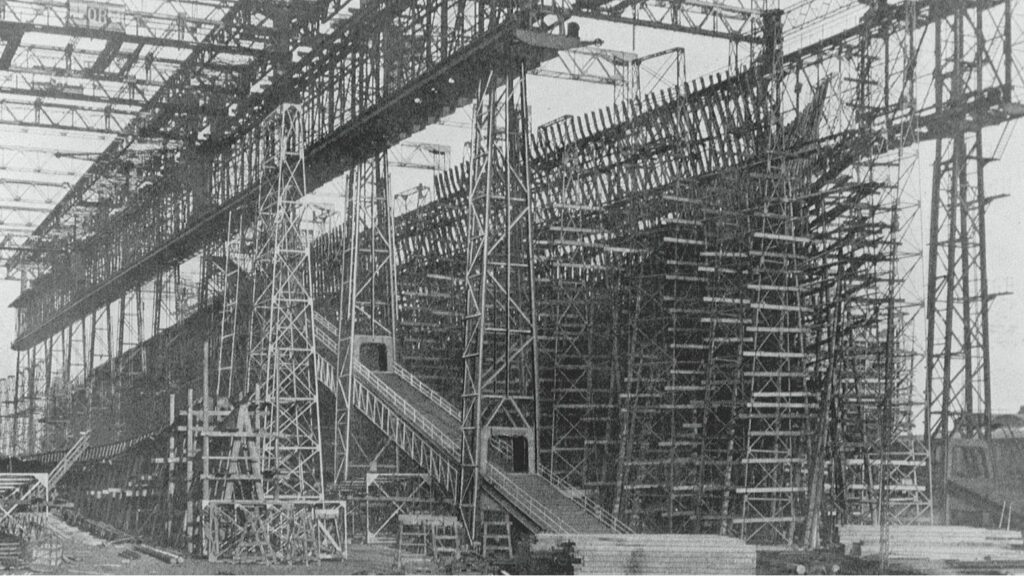
Titanic Tours: The Framing of the Titanic Last week, we looked at the visible outer part of the ship’s hull, her plating, castings, forgings, and rivets. We also discussed the way in which the individual plates were assembled. The plates, which formed Titanic’s outer skin, would not, however, have anything to attach to if not for the frames. The frames inside a ship’s hull are not visible in exterior photographs and are only somewhat evident in photographs of the interior. They are like the skeleton in a human body, giving a ship its overall shape and also providing strength and internal structure. Ships are divided by transverse frames spaced at intervals from the stem to the stern. While various numbering schemes for frames can be used, Titanic’s frames were numbered from amidships, with the exact middle frame left unnumbered. Each frame radiating from that was numbered sequentially and denoted as either forward (“F”) or aft (“A”) of the midship frame. Thus, the frame directly forward of amidships was “1F” and the one directly aft was “1A.” At the forward perpendicular, the forward-most frame was 156F. At the front of the sternpost was the aftmost frame, number 148A. The transverse frames were spaced differently in different areas, closer together at the bow (as close as 24 inches) and stern (as close as 27 inches) and further apart amidships (up to 36 inches). The closer spacing was due to the ship’s experiencing higher stresses on the hull at the ends. The frames ran from the tank top above the cellular double bottom (which formed their floor) to B deck, including the forecastle and poop decks. This formed the “box girder” of the ship’s hull, a hull form that proved incredibly strong and resistant to the high stresses of the North Atlantic routes. Each frame was composed initially of a straight steel bar that was then bent to the needed shape. The frames, once attached to the ship’s bottom, were joined by beams at each deck level. These were supported vertically by pillars and longitudinally by girders. Stringer plates were also fitted in specific areas to increase strength, with these running horizontally along the frames where the vertical distance between beams was larger (as in the holds, boiler rooms, and engine spaces). Stringers were also fitted at B-deck level for added strength. Framing of the ship would be completed before plating, as the plates would attach to the frames. Frames would subsequently be used to identify locations on the ship (you can often see a frame referenced in studies of the damage by the iceberg, for example). With the beams and pillars giving a ship the basics of its internal form, rooms and interior spaces could be constructed around them when the time came. Next Week: Making Titanic Watertight Written By: Nick DeWitt Photo Credit: Titanic Connections Archive Olympic’s framing is nearly complete in this image, showing the skeletal structure which gives the ship her overall form. This looks at her from her starboard bow, with the beginnings of Titanic just visible on the left of the frame. A close-up view of Titanic’s framing in progress
Titanic Tours: the Double Bottom
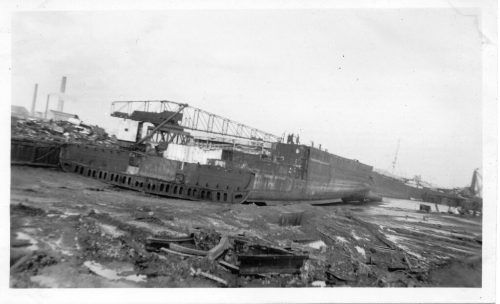
Titanic Tours: the Double Bottom An aerial view of Olympic, looking aft from the bow, showing the subdivision of the double bottom in excellent detail When we discuss Titanic’s watertight subdivision, one of the often-overlooked aspects of her construction is the double bottom. Titanic had what could be called a second or inner skin within the visible exterior hull plates that made up her bottom. As we discussed last week, Titanic had a vertical keel that extended upward from the keel plates themselves. This formed the center point for the double bottom, which took the form of a series of small compartments that formed something of a “honeycomb” at the bottom of the ship under her tank top. Each of these tiny compartments were formed by “floors” at each frame and three longitudinal structures (the keel itself and two margin plates, each located 30’ outboard on either side of the vertical keel). The spaces ranged from 63” to 75” inches in height, being thickest under the heavy reciprocating engines. Each of these “cells” or “tanks” could be utilized for various purposes, from ballast to storage of water. They also were important for Titanic’s stability, preventing water from sloshing around large spaces along the bottom of the ship. Most importantly when it comes to safety features, this cellular bottom and the inner skin it created would help the ship survive grounding collisions where the bottom of the ship was opened to the sea by some obstruction. Rather than a large compartment being opened to the sea and perhaps completely disabling the liner, a small void space would be opened up, giving water much less space to roam free and preventing the ship’s vital components from being damaged or put out of service. As with the keel, Titanic’s double bottom structure can still be viewed today on the two pieces of double bottom that may have formed the final connection between the ship’s bow and stern sections as the liner plunged to the ocean floor. Next Week: Titanic’s Hull Written By: Nick DeWitt Photo Credits: Titanic Connections Archive A view of the Olympic’s double bottom during her scrapping in the mid-1930s from the Titanic Connections Archive
