
Titanic Tours – The Bridge
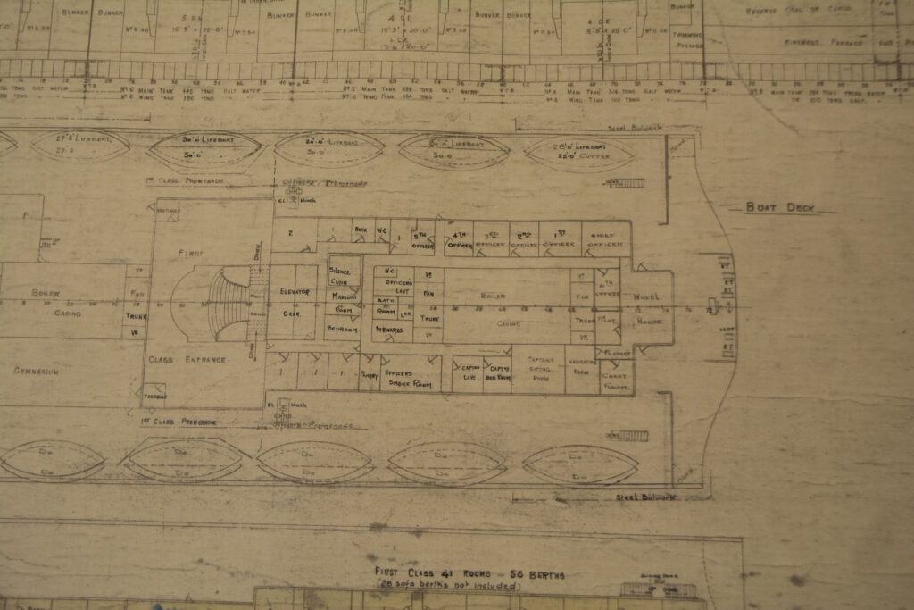
Titanic Tours – The Bridge A Titanic Connections Feature by Nicholas Dewitt The General Arrangement (GA) plans for the bridge area. These would be similar for both Olympic and Titanic, but Olympic was initially equipped with a curved-front Wheelhouse. Titanic’s was flat-fronted as presented here. The brain of any vessel at sea is her bridge. In the case of Titanic, the bridge is where some of the most consequential actions of 14 April 1912 occurred. This week, we’re heading there to take a look at this important space. Before we begin, a little historical note on the term “bridge.” Sailing vessels did not have a bridge, being instead navigated and commanded from the quarterdeck where the ship’s wheel could be found. But with the arrival of steam power and the equipping of ships with paddle boxes on their sides, the ship’s engineers needed a way to easily get from one paddle box to another and inspect the machinery. This took the form of a raised platform that stretched between the two boxes, forming a literal bridge. When paddles disappeared in favor of the screw propeller, the bridge stayed and became home to the ship’s command and navigating instruments. On the Olympic-class liners, as with other liners of the era, the bridge was located forward atop the superstructure. Denoted by a series of nine rectangular windows at the front center of the boat deck, the bridge encompassed a Navigating Bridge just behind the windows, an enclosed Wheelhouse situated behind that space, and encompassed the swept-back wings on either side that ended in a covered “cab” where officers could observe goings on below and to either side. We will explore all of these spaces in today’s tour. Connected to the Wheelhouse were a Chart Room, a Navigating Room, and quarters for a harbor pilot. We will explore these rooms at a later date. Navigating Bridge Each space above had a specific function to perform. Let’s begin with the Navigating Bridge. This space contained five order telegraphs, a wheel, and compass binnacle. There were also two small fold-down tables on either side wall that could be used for charts. While the wheel here was only manned when traveling near shore, the five telegraphs could and would be utilized to communicate with the various engine spaces throughout a voyage. The two outermost telegraphs were connected to the engine room to transmit orders for the speed of the ship. Each of the drums had an indicator for dead slow, slow, half astern, full astern, dead slow, slow, half ahead, full ahead, stop, stand by astern, and stand by ahead. The port handle of these telegraphs would transmit orders for the port engine and the starboard handle would do the same for the starboard engine. These two telegraphs were also connected to one another, so orders need only be “rung down” on one of the telegraphs. A third engine order telegraph was located directly to port of the wheel. This was the emergency telegraph. It had an independent connection to the engine room in case of the failure of the pair of main engine order telegraphs, but was otherwise the same in function. The two remaining telegraphs were for use when the ship was being docked or was near shore. These communicated with the Docking Bridge located on the poop. One was similar to the three engine order telegraphs, but would relay those commands to the Navigating Bridge from the Docking Bridge. The other had a dual set of commands on the side dials, one inner and one outer. Communicating both ways, the Navigating Bridge could send docking commands such as “Let Go Tug” or “Slack Away Stbd.” The Docking Bridge could also indicate information like “All Clear Stbd” or “Not Clear Stbd” to the Navigating Bridge. At the center of the Navigating Bridge stood the wheel and compass binnacle. The teak binnacle contained a 10” Kelvin-White compass. This was one of four main compasses aboard the Olympic-class ships, with the others being located in the Wheelhouse, a midships Compass Platform, and on the Docking Bridge. The compass inside the binnacle would have been lighted for easy viewing at night. Behind the compass binnacle was the ship’s wheel, one of three that could be used to steer the ship. This wheel, made of teak and measuring 3’ 9” in diameter, was mounted on a 34” high brass pedestal. This wheel was manned only when the ship was close to shore, but was connected to the telemotor in the Wheelhouse, which then connected it to the steering gear under the poop. The Navigating Bridge was fronted by nine large windows, with one of the ship’s bells mounted outside and above the center window. Two more windows opened out from the sides of the space, in line with the main engine order telegraphs. The General Arrangement (GA) plans for the bridge area. These would be similar for both Olympic and Titanic, but Olympic was initially equipped with a curved-front Wheelhouse. Titanic’s was flat-fronted as presented here. BRIDGE WINGS Accessed from the open sides of the Navigating Bridge were the two bridge wings, each with a steel bulwark swept back toward an overhanging bridge wing cab with windows on three sides. This area would be used for observation by officers on watch, providing an unobstructed view forward, to either side, and, thanks to the cab extending slightly over the side, downward to the sea. Immediately outside of the Navigating Bridge, nestled in the space where the bulwark met with the walls of the bridge, a pillar stood for use in mounting a pelorus. Also known as a “dumb compass,” a pelorus was used at times to take bearings. The pillar allowed it to be mounted above the bulwark for this purpose. Also of use in navigating the ship were the wing cabs, each of which was equipped with the sidelights used in navigation (red to port and green to starboard). These were designed so that they could each be
Titanic Tours – The Funnels
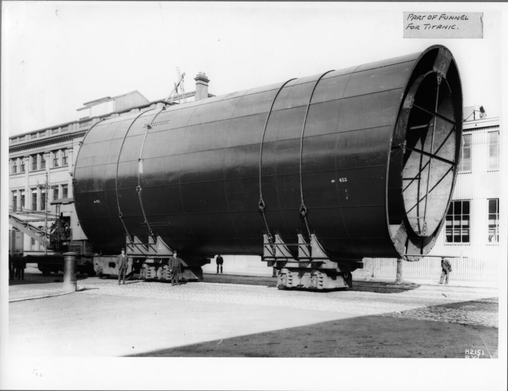
Titanic Tours – The Funnels Photographs of a profusion of colorful funnels poking above the piers of New York Harbor are some of the most well-known images of the era of the luxury liner. A ship’s funnels, while an extremely functional necessity in most cases, can also become iconic, immortalized as baubles for passengers to purchase. Today, these are highly sought-after collectibles. Funnels are not a purely visual element of a ship, however. While the look and number of funnels can sometimes be put down to a stylistic choice, funnels came into existence and have remained a key component of non-nuclear ships for an important reason: to vent the gasses, cinders, and smoke generated by a ship’s engines up and away from the decks and the passengers and crew who roamed them. The history of liners is peppered with examples of ships, such as Norddeutscher Lloyd’s Bremen and Europa, that had their funnels made taller when the too-squat models initially fitted failed to do this basic task well. Titanic, as readers probably are aware, had four funnels atop her superstructure. Each of these were oval shaped, measuring 24’ 6” in diameter running fore to aft and 19’ in diameter running port to starboard. While they were level with one another at the top, the uneven height of the deckhouses above the boat deck meant that they rose to various heights, from 70’ for the first funnel to 73’ for the fourth to 74’ for the second and third funnels. The funnels were raked gracefully back, both for style and function, and, unlike the Cunarders Lusitania and Mauretania, spaced evenly and widely along the superstructure. This gave the Olympic-class ships a more yacht-like, graceful appearance than the greyhound racer profiles of the Cunarders. The funnels were also where the ship’s whistles were located, mounted on the forward side of each funnel. These were reached by a ladder that ran up the front of the funnel. Only the whistles on the first and second funnels were operational, those on the third and fourth funnels being purely decorative to ensure all four funnels looked uniform. Copper steam escape pipes ran up the fronts and backs of each funnel as well. It was from these pipes on the night of 14 April 1912 that steam loudly escaped as the liner came to her final stop, temporarily deafening those on deck. Funnel colors were important for identifying a ship with her company. As the shipping world expanded, each line developed their own color scheme. The White Star Line had adopted an 18’ tall black band at the top with the rest of the funnel painted in a color known as “White Star Buff.” The exact shade of this color will probably never be known for certain, and is believed to have varied somewhat from painting to painting and throughout the company’s existence. While model makers and artists make their own choice as to how best to represent this color in their creations, the easiest way to describe the color is as a pale orange-yellow. Researcher Robert Read has done an authoritative article on the likely formulations of this color which is linked below for those interested. The exterior, however, is only a small piece of the story here. The funnels each served various functions for the ship, entailing a varied structure inside each. The exterior tube that can be seen is actually fitted over and connected to an internal tube. This tube was the “working” part of the funnel, designed to conform to the job it was expected to perform. The first three funnels performed the expected function of funnels everywhere: venting the exhaust gasses and cinders from the ship’s six boiler rooms, with each funnel servicing two of these spaces. Each of these sets of boiler rooms comprised a different amount of fire grate area (the space in which the coal was actually burned to power the ship), so each funnel had a slightly different design. Each boiler’s uptakes stretched toward the center of the ship, where they gradually combined to be vented up through that funnel. The ship’s fourth funnel has been the source of much confusion over the years. While it is true that only the first three funnels were required for the Olympic-class liners to operate, this fourth iteration did serve in important ways. From a decorative perspective, the fourth funnel conveyed the idea of power and size to a traveling public that had become accustomed to the biggest and fastest ships sporting four funnels. It also allowed for a balanced look, with four funnels spacing evenly along the ship’s profile in a way that would not have been possible with just three. If it had stopped there, perhaps the fourth funnel could be put down as a true “dummy.” It could be considered as little more than an ornament added for aesthetic reasons only. This funnel, however, had a functional purpose as well. While not required for the ship’s boiler rooms, the fourth funnel provided ventilation for exhaust from the ship’s galley spaces, the extra tariff restaurant on B deck, the first class Smoking Room, the Turbine Engine Room, and various other spaces throughout the ship. While these spaces could possibly have been ventilated through other methods, being able to combine them into a funnel was much more effective. Each funnel was held in place by 12 stays or shrouds, each measuring 4” in circumference and with six located on each side of the funnel. These were secured at the base of the black-painted part of the funnel at the top and to various pad eyes on the deck at the bottom. Further Reading: Robert Read’s research on White Star Buff can be found here: http://www.titanic-cad-plans.com/whitestarbuff.pdf Content by: Nick Dewitt Funnel Installation This photograph of one of Titanic’s funnels before installation shows the way in which the funnel structure was subdivided and supported. Olympic’s Boat Deck This photograph from Olympic shows how the shrouds attached to both the upper
The Voice of Sheila Macbeth Mitchell
THE VOICE OF SHEILA MACBETH MITCHELL This exclusive voice recording of Sheila Macbeth Mitchell was brought to you exclusively by Titanic Connections thanks to the Imperial War Museum (IWM). This audio is not for reproduction and may not be reposted anywhere.
Titanic Tours: Titanic’s Decks
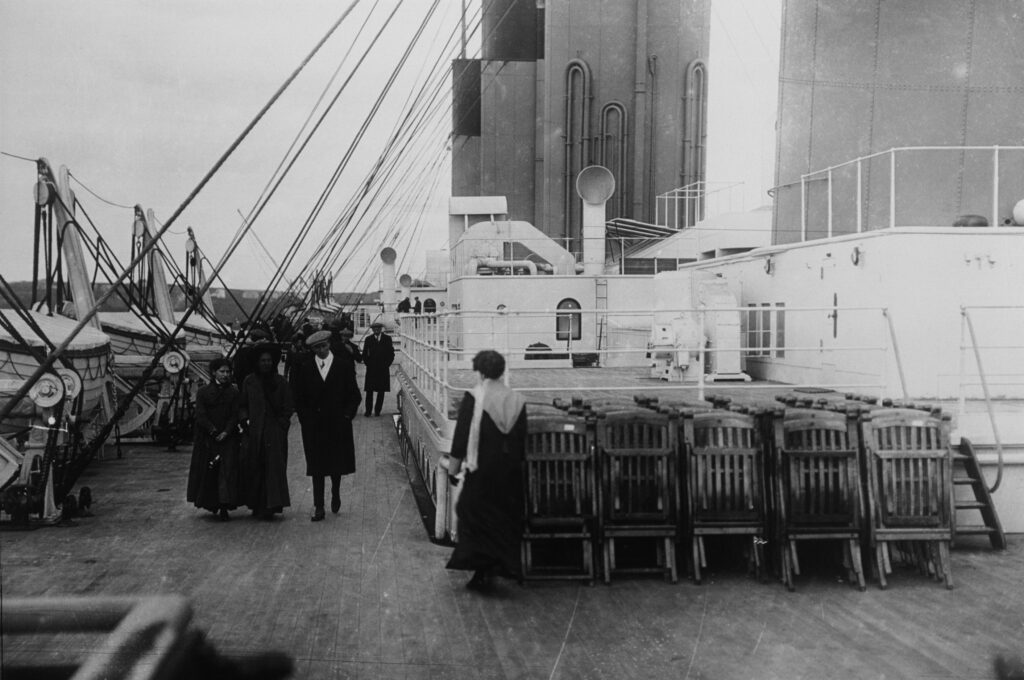
Titanic Tours: Titanic’s Decks Most Titanic enthusiasts and historians dream of the chance to walk the decks of the ship and experience her in all her glory. We imagine ourselves strolling the promenade deck or examining the boats on the boat deck. This week, we’ll explore how those decks were made. A few weeks ago, we looked at Titanic’s frames and how they formed the steel skeleton of the ship, rising vertically to form what we think of as ribs. To these frames and the beams emanating from them, the decks would be attached. It’s important to note that Titanic’s decks were not “flat” by any stretch. They would have had a gentle transverse rise in the center of about three inches. It would have been hardly noticeable to passengers unless they were paying close attention, but it was designed to ensure that water that accumulated due to wave action could easily find it’s way to the sides of the ship and then out the scuppers cut into the hull bulwarks. This rise, called “camber” was present on all of Titanic’s decks. The decks themselves were constructed of steel plates and were assembled along the same lines as the hull, with the in and out system of overlapping edges present. As discussed last week, expansion joints were incorporated into the decks above B deck to allow the rigid steel movement in a seaway. In this way, the decks could flex where needed, but otherwise they were as rigid as the hull itself, while not providing additional strength to the hull girder. The more visible and better-known element of the decks was the wooden sheathing over the steel plates. The wooden planking on her decks was not just decorative, it served a number of important purposes. As steel decks would warm in the sun or chill in the cold, the wood provided a more-uniform temperature for places where passengers and crew would walk regularly. Since wood does not transmit temperature changes, it also helped maintain the temperature inside the ship. Titanic and her sisters incorporated both pitch pine and yellow pine deck planks. The pitch pine was used in high use/high stress areas only, with the yellow pine everywhere else. Planks were typically three inches thick and five inches wide, varying in length to suit the space, and secured to the steel by heavy iron bolts. Once laid, the planks were caulked to help keep them in place. Inside the ship, wood planking was also used in some spaces, but tiles (both linoleum and ceramic), carpet, and parquet could also be found in various spaces. Ceramic tiles were often used in areas where moisture would often be present (lavatories and the swimming pool, for example),while linoleum was found in many passageways, staterooms, and public spaces. Today, tiles from Titanic’s sister Olympic are highly collectible. Next Week: Titanic’s Deckhouses Written By: Nick DeWitt Photo Credit: Titanic Connections Archive Photo Captions: 1: Passengers walk along the boat deck, where pitch pine planks can be clearly seen 2: The well-known (and now highly collectible) two-color tiles found in many parts of the ship are seen here in Olympic’s first class Smoking Room 3: Octagonal tiles are discernable here lining the deck around Olympic’s swimming pool
Titanic Tours: The Framing of the Titanic
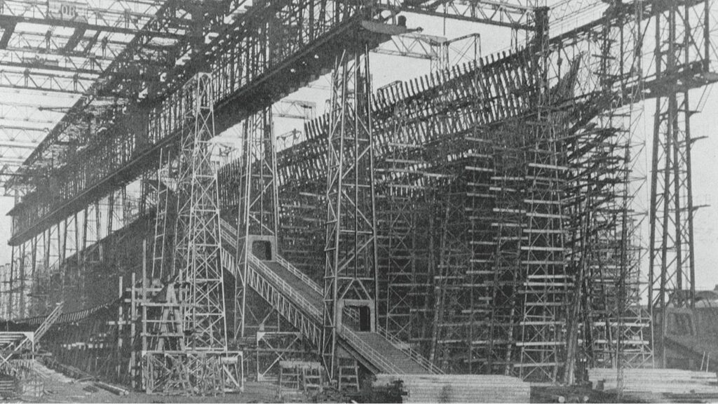
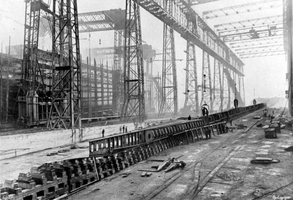
Titanic Tours: The Framing of the Titanic Last week, we looked at the visible outer part of the ship’s hull, her plating, castings, forgings, and rivets. We also discussed the way in which the individual plates were assembled. The plates, which formed Titanic’s outer skin, would not, however, have anything to attach to if not for the frames. The frames inside a ship’s hull are not visible in exterior photographs and are only somewhat evident in photographs of the interior. They are like the skeleton in a human body, giving a ship its overall shape and also providing strength and internal structure. Ships are divided by transverse frames spaced at intervals from the stem to the stern. While various numbering schemes for frames can be used, Titanic’s frames were numbered from amidships, with the exact middle frame left unnumbered. Each frame radiating from that was numbered sequentially and denoted as either forward (“F”) or aft (“A”) of the midship frame. Thus, the frame directly forward of amidships was “1F” and the one directly aft was “1A.” At the forward perpendicular, the forward-most frame was 156F. At the front of the sternpost was the aftmost frame, number 148A. The transverse frames were spaced differently in different areas, closer together at the bow (as close as 24 inches) and stern (as close as 27 inches) and further apart amidships (up to 36 inches). The closer spacing was due to the ship’s experiencing higher stresses on the hull at the ends. The frames ran from the tank top above the cellular double bottom (which formed their floor) to B deck, including the forecastle and poop decks. This formed the “box girder” of the ship’s hull, a hull form that proved incredibly strong and resistant to the high stresses of the North Atlantic routes. Each frame was composed initially of a straight steel bar that was then bent to the needed shape. The frames, once attached to the ship’s bottom, were joined by beams at each deck level. These were supported vertically by pillars and longitudinally by girders. Stringer plates were also fitted in specific areas to increase strength, with these running horizontally along the frames where the vertical distance between beams was larger (as in the holds, boiler rooms, and engine spaces). Stringers were also fitted at B-deck level for added strength. Framing of the ship would be completed before plating, as the plates would attach to the frames. Frames would subsequently be used to identify locations on the ship (you can often see a frame referenced in studies of the damage by the iceberg, for example). With the beams and pillars giving a ship the basics of its internal form, rooms and interior spaces could be constructed around them when the time came. Next Week: Making Titanic Watertight Written By: Nick DeWitt Photo Credit: Titanic Connections Archive Olympic’s framing is nearly complete in this image, showing the skeletal structure which gives the ship her overall form. This looks at her from her starboard bow, with the beginnings of Titanic just visible on the left of the frame. A close-up view of Titanic’s framing in progress
Titanic Tours: the Double Bottom
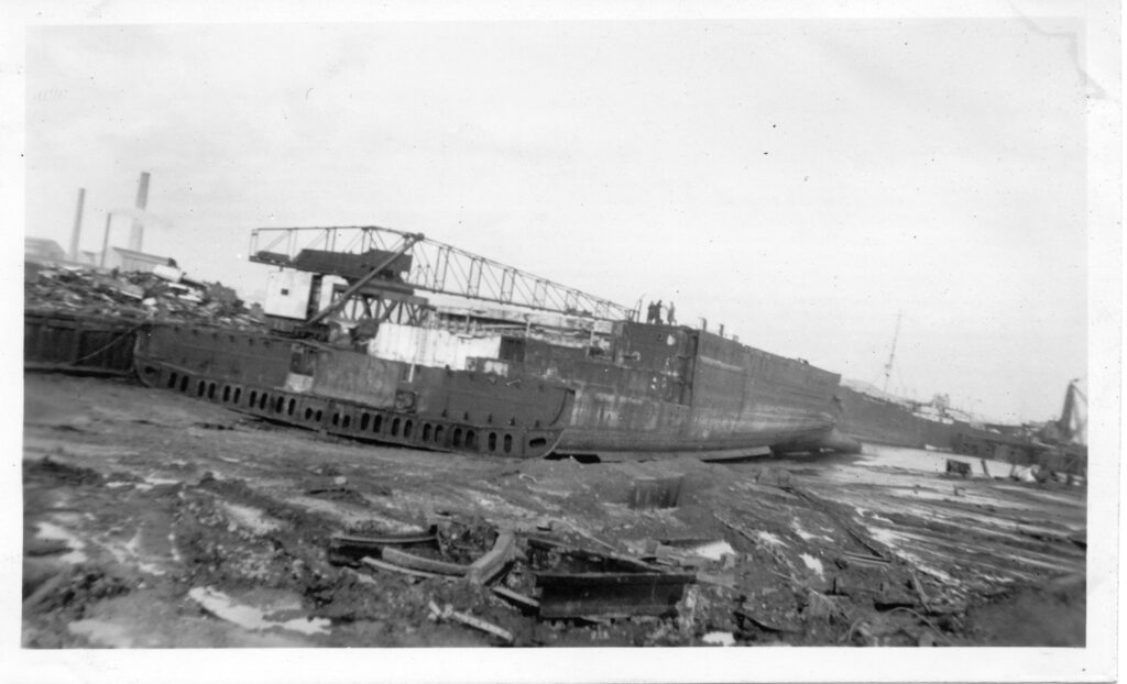
Titanic Tours: the Double Bottom An aerial view of Olympic, looking aft from the bow, showing the subdivision of the double bottom in excellent detail When we discuss Titanic’s watertight subdivision, one of the often-overlooked aspects of her construction is the double bottom. Titanic had what could be called a second or inner skin within the visible exterior hull plates that made up her bottom. As we discussed last week, Titanic had a vertical keel that extended upward from the keel plates themselves. This formed the center point for the double bottom, which took the form of a series of small compartments that formed something of a “honeycomb” at the bottom of the ship under her tank top. Each of these tiny compartments were formed by “floors” at each frame and three longitudinal structures (the keel itself and two margin plates, each located 30’ outboard on either side of the vertical keel). The spaces ranged from 63” to 75” inches in height, being thickest under the heavy reciprocating engines. Each of these “cells” or “tanks” could be utilized for various purposes, from ballast to storage of water. They also were important for Titanic’s stability, preventing water from sloshing around large spaces along the bottom of the ship. Most importantly when it comes to safety features, this cellular bottom and the inner skin it created would help the ship survive grounding collisions where the bottom of the ship was opened to the sea by some obstruction. Rather than a large compartment being opened to the sea and perhaps completely disabling the liner, a small void space would be opened up, giving water much less space to roam free and preventing the ship’s vital components from being damaged or put out of service. As with the keel, Titanic’s double bottom structure can still be viewed today on the two pieces of double bottom that may have formed the final connection between the ship’s bow and stern sections as the liner plunged to the ocean floor. Next Week: Titanic’s Hull Written By: Nick DeWitt Photo Credits: Titanic Connections Archive A view of the Olympic’s double bottom during her scrapping in the mid-1930s from the Titanic Connections Archive
A Titanic Tour: From the Keel Plates up
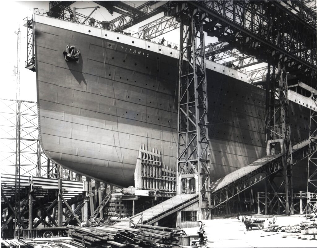
A Titanic Tour: From the Keel Plates up On 31 March, 1909, the first plates of Titanic’s keel were laid in Slipway No. 3 at Harland & Wolff in Belfast. The keel-laying is the first event in the life of a new ship. Titanic’s keel plates are described in the magisterial “Titanic: The Ship Magnificent” as follows: “Flat-plate design, formed by a single thickness of plating 30/20 inch thick and reducing to 24/20 inch thick toward the ends. The keel plate was 52 inches wide at its broadest point.” A “slab bar” of 19 1/2 inches by 3 inches provided extra strength below this plate. This also, as the authors note, protected the keel plates from damage via grounding and dry-docking. The “vertical keel,” which rose from this line of plate, helped form the central part of the ship’s double bottom and created what is commonly known as the ship’s “backbone.” This spine varied in thickness from 63 inches to 75 inches below Titanic’s gargantuan reciprocating engines. Looking at the ship, the keel is discernible from the rest of the bottom of the hull as a wide strip of riveted plate running down the center line. Initially resting on wooden blocks, like those that can still be seen today in the Thompson Graving Dock in Belfast, the keel would eventually be attached to the “floors,” which formed the outer skin of Titanic’s bottom and the lower plating for her cellular double bottom. Growing first outward and then upward, the hull would eventually radiate out from her keel and form the “box girder” of her hull, an incredibly strong and resilient design that had become common during the 19th century move to iron and steel construction. While Titanic’s keel is not the most glamorous part of her construction, it is one of the most important individual pieces of the ship. Given the immense hogging stresses that the hull was placed under as she sank upright (rather than the more common capsizing that usually is present during a sinking), the strength of her keel determined how long her hull maintained its integrity. With Titanic surpassing even Thomas Andrews’ on-site calculations about the time she could remain afloat, her backbone can be said to have been incredibly resilient. It is ironic that Titanic has been derided in some circles as a “weak” or “poorly constructed” ship. Nothing could be further from the truth. Titanic’s keel was perhaps the last part of the ship to part during her breakup. Two surviving sections of her double bottom were located in the mid-2000s and have since been extensively studied. The keel bar itself can be seen in photos of the sections. Next Week: The Double Bottom Written By: Nick DeWitt Photo Credit: Titanic Connections Archive
A New Titanic Connections Feature: Titanic Tours
TITANIC CONNECTIONS FEATURE: TITANIC TOURS When Titanic was constructed at Harland and Wolff from 1909 through 1912, she would become the largest moving object ever made by man, edging out her elder sister Olympic thanks to additional features that were included in her after experience with Olympic showed various possibilities for improvement. Titanic Connections, using original photographs of the Titanic and her sister Olympic, as well as building plans, digital recreations, and other sources, will be taking our visitors on a tour of the ship. Every Tuesday, Titanic Connections’ historian Nick DeWitt will touch on a particular feature of the Titanic, starting with her keel plates and finishing eventually with the tops of the masts, funnels, and the wireless aerial. As Bruce Ismay said in James Cameron’s 1997 epic “Titanic,” the tour will be “from the keel plates up!’ We hope you’ll enjoy this feature and we look forward to bringing it to you each week. If you have a feature of the ship you want to make sure we touch on, please let us know! While the weekly tours will be done from the bottom of the ship to the top, we are always open to suggestions about what you’d like to hear more about when we get to that part of the ship! PHOTO CREDIT: Robert Welch, Harland & Wolff (now in the public domain)
